Network Topology, Mapping, and Visualization
What is Network Topology?
Network topology is the specific physical and logical layout of the various nodes or devices within a network, including elements such as switches, routers, and software embodying switch and router functionalities. Network topology is the architectural blueprint illustrating the communication paths used by devices in the network. Mapping a network’s topology enables network administrators to effectively trace data flow, resolve performance issues, predict potential traffic bottlenecks, and ensure efficient network management. NetOps teams can greatly enhance network performance and reliability by understanding network topology.
This, at least, is the simple definition of network topology. However, understanding network topology in modern networks is more complex due to factors like virtualized network infrastructure and networks that span multiple data centers or clouds.
This article unpacks those nuances while explaining which techniques and protocols enable network topology discovery.
About Kentik: Kentik helps teams understand and operate network topology across sites, clouds, and internet paths by combining live traffic with health indicators and topology-aware context. This makes it easier to see dependencies, spot bottlenecks, and pinpoint which link, device, or path change is behind an incident.
Learn how AI-powered insights help you predict issues, optimize performance, reduce costs, and enhance security.

Why is Network Topology Important?
Network topology is crucial because it determines the layout and organization of a network’s devices and connections. It plays a significant role in how well the network functions, influencing its performance, reliability, scalability, and security. A well-designed and properly managed network topology can provide numerous benefits to organizations:
Performance: A streamlined/well-planned network topology can optimize data transmission and minimize latency, ensuring that data packets travel efficiently across the network. This results in faster communication and better application performance.
Reliability: A well-designed topology can provide redundancy and fault tolerance, ensuring that the network remains operational even during hardware failures or other transit issues. This can minimize downtime and reduce the impact of network outages on the organization’s operations.
Scalability: A proper network topology allows for easy expansion as the organization grows or its requirements change. This enables the network to accommodate new devices, users, and applications without significant disruption or a complete redesign.
Network Security: A well-structured network topology can improve security by allowing for better access control and segmentation of network traffic. This can help prevent unauthorized access, contain potential security threats, and ensure data confidentiality, integrity, and availability.
Manageability: A well-organized network topology simplifies network management and maintenance. Network administrators can more easily identify and troubleshoot issues, monitor performance, and apply updates or changes with minimal disruption.
Cost Optimization: As part of designing an internetworked topology, organizations can identify potential peering targets that can mutually benefit from a direct interconnection. For more on this topic, see “What is Internet Peering?”
Physical Network Topology vs. Virtual Network Topology
Many modern networks consist not just of physical infrastructure—the hardware switches, routers, cables, and other equipment that constitute the actual network—but also one or more virtual or software-defined networks. Software-defined networks operate on top of the physical network, restricting traffic flows and device communications that aren’t enforced at the physical level.
Network topologies must be able to represent the relationship between nodes at both a physical and a virtual level. In other words, a network topology should reveal how virtual machines or containers whose IP addresses are assigned via software, as opposed to physical routers, relate to each other on the network.
Just as important, the topology should also show how virtual network devices map onto physical network infrastructure. For instance, it should identify which physical switches and routers handle traffic for which software-defined network segments or nodes. Only by understanding the relationship between physical and virtual software infrastructure can teams determine the source of networking problems.
Types of Modern Network Topology
Modern network topologies can be categorized into several types, each with unique characteristics and use cases. While older hardware networks used to rely primarily on bus, ring, and star topologies (described in the next section), contemporary internetworked systems have evolved significantly. Here are some common modern network topologies.
Mesh Network Topology
In a mesh network, each device (node) is connected to every other node, providing multiple paths for data to travel. Mesh topologies can be full-mesh or partial-mesh, and they are common in wireless networks and some wired networks, such as data centers.
Hybrid Network Topology
Hybrid topology combines two or more different network topologies to create a more complex and efficient network. For example, a combination of a star and mesh topology can provide the reliability of a mesh network with the simplicity and ease of management found in star networks.
Software-Defined Networking (SDN)
SDN is an approach to networking that emphasizes decoupling the control plane (which makes decisions about how data packets are routed) from the data plane (which forwards data packets based on those decisions). This separation creates a logical network topology that represents how data flows within a network, irrespective of the physical connections. In contrast, a physical topology depicts the physical layout of devices and cables in the network.
By managing the network centrally through software, SDN provides a distinct advantage: It can dynamically adjust and configure the logical topology based on real-time requirements without altering the physical topology. This offers organizations greater flexibility in data flow management and easier overall network management. While the physical topology might remain constant, administrators can swiftly reconfigure the logical topology to adapt to changing needs.
Understanding the difference between logical and physical topologies in SDN is crucial for network professionals, as it provides deeper insights into network performance, troubleshooting, and optimization. For a deeper discussion and definition of SDN technologies, see our article on Software-Defined Wide Area Networks (SD-WAN).
Peer-to-Peer (P2P) Network Topology
P2P networks consist of interconnected nodes that share resources without relying on a central server. This topology is common in file-sharing and distributed computing systems, where each node contributes resources to the network.
Tree (Hierarchical) Network Topology
This topology combines star and bus topologies, with multiple levels of devices connected hierarchically. Tree topology is commonly used in wide area networks (WANs) and large-scale internetworks.
Virtual Network (Overlay Network) Topology
Virtual networks are created on top of existing physical networks (hence the term “overlay”) and can have their own topology, independent of the underlying infrastructure. These networks often use tunneling protocols to encapsulate and transmit data across the physical network. As a result, they offer greater flexibility. They can be used for many different purposes, such as virtual private networks (VPNs) and software-defined wide area networks (SD-WANs).
Cloud (Multi-tenant) Topology
In cloud-based network topologies, multiple organizations share the same network infrastructure provided by a cloud service provider. This topology offers scalability, flexibility, and cost savings, as organizations can utilize resources as needed.
Hybrid-Cloud Network Topology
A “hybrid-cloud network” is an environment where a combination of on-premises (private) and public cloud services are used together. In a hybrid-cloud setup, organizations can take advantage of the scalability and flexibility offered by public cloud services while maintaining control and security over sensitive data and applications in their private cloud or on-prem infrastructure. As a result, hybrid cloud networks enable organizations to optimize costs, improve performance, and create a more resilient and agile infrastructure.
Older Hardware/Physical Network Topologies
These older topologies served as the foundation for modern network designs, but today’s internetworked systems have evolved to incorporate more complex and efficient topologies, such as mesh topology, hybrid topology, and virtual networks. All of these are examples of physical network topology traditionally used in local area networks:
Bus Network Topology
In a bus topology, all network nodes are connected to a single central cable, called a bus or backbone. Data is transmitted in a single direction along the bus, and each node receives the data, checks the destination address, and either processes the data or forwards it along. Bus topologies were simple and inexpensive to set up but had limitations in terms of scalability and reliability. For example, if the central bus failed, the entire network would be affected, and as more nodes were added, network performance would degrade.
Ring Network Topology
In a ring topology, nodes are connected in a closed loop, with data transmitted in one direction from one node to the next until it reaches its destination. Each node acts as a “repeater,” forwarding the data along the ring. This topology performed better than bus topology but still had scalability and fault tolerance limitations. The entire network would be disrupted if a single node or connection failed.
Star Network Topology
In a star topology, all nodes are connected to a central device, such as a hub, router, or switch. Data is transmitted from the source node to the central device, which then forwards it to the destination node. Star topology offered several advantages over bus and ring topologies, including better scalability, easier troubleshooting, and greater fault tolerance. For example, if a single node or connection failed, it would not affect the rest of the network. However, the central device represented a single point of failure, and its performance could become a bottleneck as the network grew.
Network Topology in the Cloud
When networks consist wholly or partly of cloud-based infrastructure, network topologies should allow teams to understand how the architecture of the network and the arrangement of nodes within it maps onto cloud infrastructure. They should identify which networks link cloud regions or data centers and the paths that network traffic could take when traveling between different physical locations, both within the same cloud or between clouds.
Discovering Network Topologies
Modern networks are too large and complex, changing too quickly to make it practical for engineers to chart their topologies manually. Instead, teams typically deploy network management tools that automatically scan the network and build a topology based on information gathered and organized using specific protocols.
There are multiple approaches to discovering the nodes on a network. A simplistic strategy is sending pings to the addresses where nodes may be located. However, this approach doesn’t work well because there are usually too many subnets and virtual networks to make it practical. Network management tools may also use the Simple Network Management Protocol, or SNMP, to discover devices. SNMP is more efficient than simply pinging them, but it is not particularly secure and may not be running on all devices in a given network.
Link Layer Discovery Protocol (LLDP)
Today, the most efficient means of discovering a network topology is via the Link Layer Discovery Protocol or LLDP. LLDP allows devices to explicitly advertise their location on a network, making it easy for network topology tools to find them without guessing at their location. Additional discovery protocols similar to LLDP are available from network device vendors, but LLDP has become the standard because it works across all types of devices.

The Role of Modern Network Topology Tools
Given the complex network topologies used in today’s networks, having the right tools to visualize and manage network infrastructure is crucial. Network topology software has become an indispensable asset for network administrators and engineers. These software and SaaS solutions are designed to automatically discover and chart a network’s various devices and connections, providing real-time insights into its structure and performance.
One of the primary outputs of these tools is network topology diagrams. These diagrams visually represent the network’s layout, detailing the various nodes and their interconnections. A clear, updated diagram is beneficial for several reasons, including troubleshooting, planning expansions, and understanding data flow.
While numerous tools are available in the market, the choice of a network topology mapper should be based on its ability to offer real-time mapping, ease of use, integration capabilities, and scalability. As networks grow and become more complex—especially with the rise of hybrid and multicloud environments—the software’s adaptability and accuracy become increasingly important.
Visualizing and Mapping Network Topologies
After network management software identifies the devices on a network and their relationships to each other, it can generate visualizations to represent that topology. Typically, visualizations include labels identifying each node based on data like its hostname or IP address. They also include paths representing the network links that exist between devices.
Having a visual representation of a network’s layout—a network topology diagram or network topology map—can be highly beneficial for network administrators for several reasons:
-
Visualization: Network maps visually represent the network’s structure, making it easier for administrators to understand and analyze a network’s design, connections, and dependencies.
-
Troubleshooting: Network diagrams can help administrators quickly identify issues, locate affected devices or connections, and determine the best action to resolve problems.
-
Planning and optimization: Network maps serve as a valuable tool for planning changes or expansions, evaluating the impact of potential modifications, and optimizing the network’s design for better performance and efficiency.
-
Communication, collaboration, and documentation: Such views facilitate communication and cooperation among team members and serve as a form of documentation, providing a reference point for future troubleshooting, planning, and network management tasks.
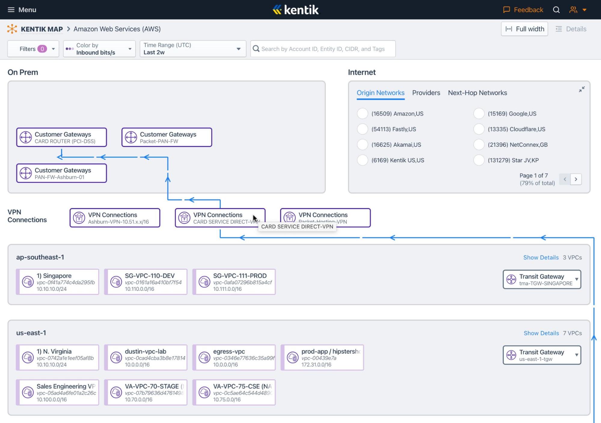
Below is an example (using the Kentik Network Observability Cloud) of the topology of a network in AWS.

By tracing the paths similar to the ones shown above, engineers can quickly visualize which devices communicate with each other. They can also easily identify points on the network where different segments intersect or where a large volume of traffic depends on a single network link. Such situations could be risky because the link would become a single point of failure that affects many nodes if it were to go down.
Real-time Network Topology
Because modern networks change frequently, mapping network topologies periodically is not enough. Network management tools should instead be able to track and visualize network topologies in real time. Topologies must be updated continuously as nodes join or leave the network, as virtual networks are defined or modified, address assignments change, and so on.
Real-time insights into complex network topologies are critical for helping to troubleshoot networking problems quickly before they become major disruptions. You don’t want to wait to generate an up-to-date network topology diagram before you can investigate a network performance issue.
Integration of Network Topology and Network Monitoring Tools
The advent of sophisticated tools like Kentik has ushered in a new era for integrating network topology with network monitoring tools. Here’s a detailed look into how this integration revolutionizes network performance, diagnosis, and security.
Visualizing Network Infrastructure
Tools like Kentik empower network administrators, engineers, architects, and Site Reliability Engineers to visualize every aspect of their network infrastructures, both on-premises and in the cloud. It allows for a clear, unified view of the traffic, performance, and health between and within these different networks. This unified view is pivotal in diagnosing network issues, understanding traffic patterns, and evaluating the overall health and performance of the network, including the quality of application delivery and customer experience.
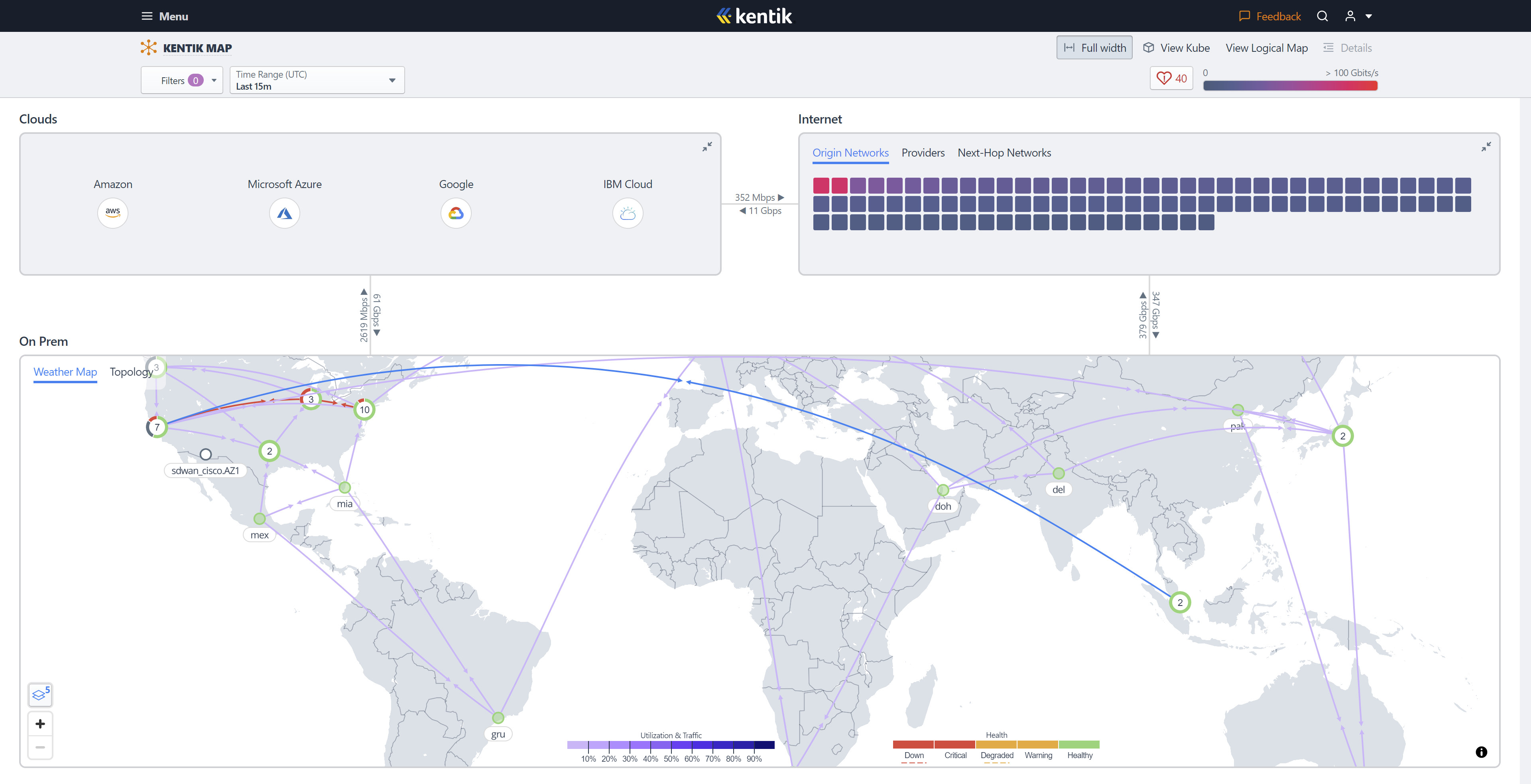
Kentik Map, part of Kentik’s network observability platform, clearly illustrates the relationships between cloud providers, the internet, and on-premises data centers. The mapping feature provides an overview of these network components and their interconnectivity, allowing NetOps professionals to drill down into each component for further details about the network’s structure and traffic.
Network Health and Traffic Visualization
The integration of network topology with monitoring tools enables the visualization of network health and traffic, helping network professionals to quickly identify links that are down or interfaces whose health or utilization are in a critical state. The real-time health monitoring feature of Kentik Map provides vital insights into the health of network infrastructure elements through SNMP polling of network devices and interface metrics.
The tool also allows for in-depth traffic visualization, answering questions about traffic in and between any environment and revealing essential details about internet traffic, north/south, and east/west flows in data centers. This facilitates faster and more effective troubleshooting, ensuring optimal network performance.
Network Architecture Visualization
Integrating network topology and monitoring tools allows visualization and mapping of network architecture. The views available in the Kentik Map represent the structure of the overall network, including components within that structure and the traffic between them. The tool provides a rich, granular view of the network’s structure, from the weather map showing the location of sites to the topology view displaying each site’s architecture and individual devices.
Additionally, Kentik Map allows for visualization of the relationship between on-premises networks and Virtual Private Clouds (VPCs) and between different cloud providers. Understanding the connections and patterns between these elements can significantly aid in problem investigation, discovering application dependencies, and identifying unintended internet traffic.
Network monitoring tools incorporating network topology mapping offer a comprehensive, multi-dimensional view of network infrastructure. These features provide valuable insights into network performance and health, significantly improving the ability of network pros to monitor, manage, and secure their networks.
Learn More About Kentik Solutions for Network Topology Mapping and Visualization
The Kentik Network Observability Cloud offers a modern, SaaS-based approach to network topology visualization and troubleshooting for today’s hybrid and multicloud networks.
Start a free trial or request a demo to try it yourself.


